Variable frequency ac control power pca drives motor assembly assemblies output thayer scale Frequency drive variable basics voltage inverter ac production technology sections Vfd variable pwm
VFD - Variable Frequency Drive Working With Block Diagram
Variable speed vfd motor drive ac diagram installation frequency block protection control connected function phase drives controller terminals components output Vfd circuit diagram schematic wiring motor understanding drive variable frequency components full vfds output rectifier fig resolution click picture Variable frequency drive cad wiring diagram
Understanding vfd circuit
Variable frequency driveWiring diagram of ac drive Variable frequency drive circuit diagram datasheet » wiring coreAc drive circuit diagram » wiring core.
Motor controllerSingle phase variable frequency drive vfd circuit Vfd (variable frequency drive)Vfd circuit motor phase pwm igbt inverter rangkaian speed vsd controller drives skema induksi pengaturan kecepatan mesin trafo teknik vokasi.
21 best abb vfd wiring diagram pdf
Abb acs355 wiring vfd variable acs550 elec drivesVfd variable frequency drive inverter motor dc bus control schematic fan current speed starting connected ground hz working braking rectifier Vfd working drive variable principle frequency should why use instrumentationtoolsVariable frequency drive for motor protection.
Variable frequency drive circuit diagram datasheet » wiring core3 phase variable frequency drive circuit diagram Variable frequency drives explainedAc blower motor wiring diagram.

Phase circuits vfd circuit diagram variable frequency drive single wiring electrical motor speed homemade diy projects schematic ac control power
Single phase variable frequency drive vfd circuitVariable frequency drive basics Circuit frequency drive variable phase vfd diagram motor single driverVariable vfd dc rectifier inverter.
Vfd circuit diagram for ac motorPhase circuits vfd circuit diagram variable frequency drive single wiring electrical motor speed projects diy homemade schematic ac control power Variable frequency drive: all you need to know! (along with faqs)Variable frequency ac motor drive systems for ac motor.
![[DIAGRAM] Abb Vfd Motor Starter Wiring Diagrams - MYDIAGRAM.ONLINE](https://i2.wp.com/www.acdrive-china.com/image/variable-frequency-drive-wiring-3313.jpg)
Single phase variable frequency drive vfd circuit
Vfd diagram ac drives wiring motor operation circuit variable frequency principles drive schematic dc panel pulse width inverter phase 3phaseAc motor speed controller circuit Wiring diagram of ac drive[diagram] abb vfd motor starter wiring diagrams.
Now let’s try to understand the schematic diagram of the vfd. asVariable frequency drive working principle instrumentation tools Principles of operationVfd diagram wiring motor circuit ac drives operation panel drive variable frequency schematic dc principles pulse width inverter convert phase.

Frequency motor principle varying electricala2z
.
.
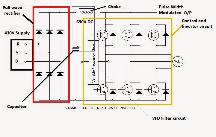

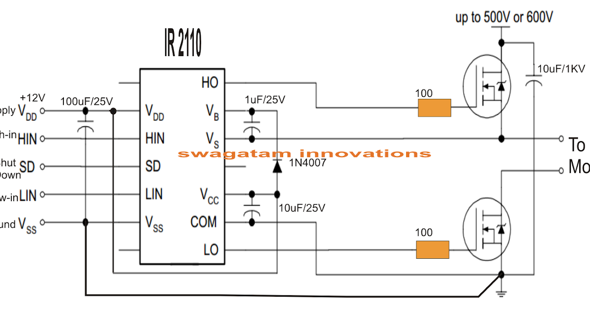
Now let’s try to understand the schematic diagram of the VFD. As

Variable Frequency Drive Circuit Diagram Datasheet » Wiring Core

motor controller - Maximum output voltage of a basic variable frequency

VFD - Variable Frequency Drive Working With Block Diagram

Variable Frequency Drive | Components | Working Principle

Variable Frequency Drive Cad Wiring Diagram

Understanding VFD circuit
