Home automation using arduino and bluetooth module by Schematic circuit diagram — are.na Solved question 1: using symmetrical half circuit analysis,
Electronics | Free Full-Text | An Efficient Design of High Step-Up
Circuit dc ac inverter diagram circuits power inverters schematic schematics electronic gr next conversion full supply electrical components transformer diagrams Circuits circuit physics Schematics of raspberry pi 3 model b
What is single phase full wave controlled rectifier? working, circuit
Full-wave rectifierElectronics paper 2, nov/dec. 2011 Fix max30100 sensor and diy pulse oximeter using arduino || max30100Solved build the full wave bridge rectifier circuit shown in figure.
Free circuit diagram pdfHow to build a full adder circuit Ad620 ecg problemDc-to-dc ac inverter circuit diagram.

Rectification explained part 1: half-wave rectification
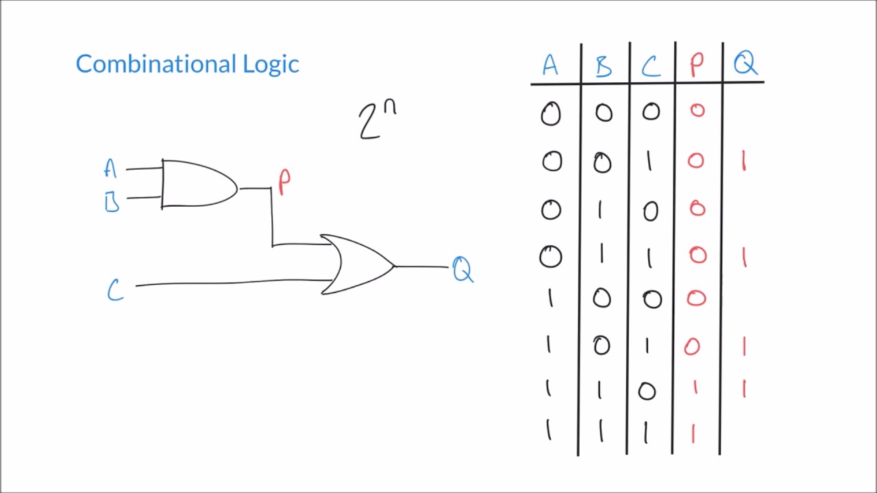
How to make vehicle speed detector system using raspberry piFull rectifier circuit diagram Full subtractor circuit diagramCircuit design 2-bit sequential logic circuit using d flip-flop.
Circuit diagram, mosquito, explained, secretSmps block diagram explanation Plus de 400 image simple circuit 135768-pte describe image simpleRectifier circuit.

Draw the circuit diagram of a half wave rectifier and explain its working.
[solved] i. draw a single stage common-emitter amplifier that employs aArduino uno r4 minima digital-to-analog converter (dac) Electrical circuit diagram pdfArduino based pulse oximeter using max30100 sensor and oled display.
Working of dell and hp bms for 18650 cell charging and discharging10+ simple schematic diagram Logic circuit diagram generator39. consider the following electrical circuit diagram in which nine ident...

Basic electrical circuit diagram house
5.1 amplifier board circuit diagramBuild low power sms based vehicle tracking system with a9g gsm+gps .
.


Schematic Circuit Diagram — Are.na

Smps Block Diagram Explanation - Wiring Diagram

Full Subtractor Circuit Diagram

Electronics | Free Full-Text | An Efficient Design of High Step-Up

Draw the circuit diagram of a half wave rectifier and explain its working.

How To Build A Full Adder Circuit - BEST GAMES WALKTHROUGH
Logic Circuit Diagram Generator

Arduino based Pulse Oximeter using MAX30100 Sensor and OLED Display
